Sunday, 16 September 2018
Friday, 14 September 2018
Sunday, 9 September 2018
Salvaging temperature and humidity dials
A few month ago my wall clock with temperature and humidity dials feel down from the wall and broke apart.
For the clock mechanism it probably was a good move (I would throw it out of window someday anyway, so loud it was). But temperature and humidity dials were quite useful, so I decided to keep them and reuse some day. And with my new and shiny Prusa i3 MK3 printer this day just came yesterday.
Making Prusa i3 MK3 a bit more stable
A couple of weeks ago I got Prusa i3 MK3 kit as my first 3D printer.
It took me two evenings and a half of Saturday to assemble it. What a nice piece of machinery it is!
I found only a couple of problems with it, first: rubber feet that just wait for any occasion to pop out of the frame when you move the printer.
There are lot of suggestion on Prusa forum how to fix it, using special printed locks, for example, or print completely new feet (what 3D printers are for anyway, if not for replicating and eventually taking over the word).
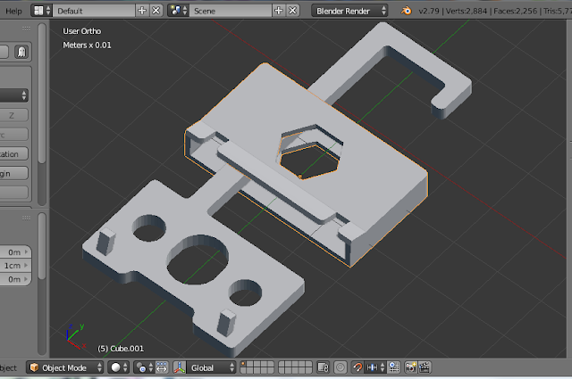
I've decided to make something myself. And here comes my second problem - last time I used blender3d years ago, so had to spent some time remembering how it works. But after a few trials I eventually got a result with suits me completely. Here it is - a simple shell for Prusa i3 MK3 feet in blender 3d:
It took me two evenings and a half of Saturday to assemble it. What a nice piece of machinery it is!
I found only a couple of problems with it, first: rubber feet that just wait for any occasion to pop out of the frame when you move the printer.
There are lot of suggestion on Prusa forum how to fix it, using special printed locks, for example, or print completely new feet (what 3D printers are for anyway, if not for replicating and eventually taking over the word).
I've decided to make something myself. And here comes my second problem - last time I used blender3d years ago, so had to spent some time remembering how it works. But after a few trials I eventually got a result with suits me completely. Here it is - a simple shell for Prusa i3 MK3 feet in blender 3d:
Monday, 6 April 2015
Making DAN - Data Acquisition Node
Transforming MMR-70 in to temperature sensing DAN - Data Acquisition Node.
Back and front (or front and back?) RFM12bs modified to provide analogue RSSI output. AA switch turns on Always Active mode, but in this case it is better to connect DAN to an external 3V power supply as CR2032 is for Power Saving mode only. Actually, in Power Saving mode this DAN draws less than 8 uA. When it wakes up for data measurement and transmission it can draw up to 14 mA, but because it happens only once a minute and takes only few milliseconds CR2032 fully restores before next session. On start up voltage goes down to 2.8V but it is back to 3.0V in about twenty minutes.
Sunday, 5 April 2015
Making shDAN - small house Data Acquisition Network
I've been experimenting with different sensors for a while now and even built a small network of sensors using RFM12bs radio transceivers. The only problem - it is very slowly moving project and sometimes I have to spend a lot of time just trying to remember what different components are doing :) So this weekend I desided to document how it works...
shDAN stands for "small/smart house Data Acquisition Network". And "small" not necessary relates to a small house, it could be just a small network in a big house :)
Why "small"? Because of the following limitations:
LBS - Listening Base Station, only collects data from Data Nodes, but never transmit anything. Useful for a standalone displays or monitoring stations.
DAN - Data Acquisition Node
NID - Node ID, base station is always 0, DANs are in 1 to 12 range, 13-15 reserved.
SID - Sensor ID, up to 8 sensors per NID. Each NIC always has two special SIDs: 0 is RF TX power, 7 indicates List of Sensors.
TOS - Type of Sensor, 1 to 15 range. For example, 1 is for Temperature, 2 Humidity and so on. For all defined types see ```dnode.h```
EOS - End of Session bit
AA - Always Active node. Usually data nodes are in sleep mode to save battery power and wake up only to do new measurement and transmit data to a base station.
shDAN uses simple time-division multiplexing schema to spread different DANs' sessions within one minute. Start of DAN's transmission can be calculated as second = (node - 1)*5 so node 1 transmits first message at 00 sec of every minute, node 2 at 05 sec of every minute and so one. A session cannot be longer than 5 seconds, last message should have EOS bit set to indicate End of Session, so base station can send messages to AA (Always Active) nodes or other nodes can transmit urgent data.
Project's page on GitHub
See SVG pictures below for details.
Latest SVG at Github
shDAN - small/smart house Data Acquisition Network
shDAN stands for "small/smart house Data Acquisition Network". And "small" not necessary relates to a small house, it could be just a small network in a big house :)
Why "small"? Because of the following limitations:
- No more than 12 Data Acquisition Nodes (DAN) per subnet
- No more than 6 sensors (zones) per Data Acquisition Node
- Messages between Base Station and Data Nodes are quite small - 13 bytes only
shDAN main components
ABS - Active Base Station, replies to time sync requests from Data NodesLBS - Listening Base Station, only collects data from Data Nodes, but never transmit anything. Useful for a standalone displays or monitoring stations.
DAN - Data Acquisition Node
NID - Node ID, base station is always 0, DANs are in 1 to 12 range, 13-15 reserved.
SID - Sensor ID, up to 8 sensors per NID. Each NIC always has two special SIDs: 0 is RF TX power, 7 indicates List of Sensors.
TOS - Type of Sensor, 1 to 15 range. For example, 1 is for Temperature, 2 Humidity and so on. For all defined types see ```dnode.h```
EOS - End of Session bit
AA - Always Active node. Usually data nodes are in sleep mode to save battery power and wake up only to do new measurement and transmit data to a base station.
shDAN uses simple time-division multiplexing schema to spread different DANs' sessions within one minute. Start of DAN's transmission can be calculated as second = (node - 1)*5 so node 1 transmits first message at 00 sec of every minute, node 2 at 05 sec of every minute and so one. A session cannot be longer than 5 seconds, last message should have EOS bit set to indicate End of Session, so base station can send messages to AA (Always Active) nodes or other nodes can transmit urgent data.
Project's page on GitHub
See SVG pictures below for details.
shDAN topology
Sunday, 29 March 2015
Making low-power version of MMR-70
I use modded version of Sony Ericsoon MMR-70 for different projects. It is cheap - less than a euro delivered and in addition to quite capable AVR controller Atmega 32L it has FM radio transmitter with RDS support, 32kHz crystal used together with FM radio and orange LED.
For remote temperature sensor powered by CR2032 battery I've stripped down all unused components - FM radio transmitter, 2.8V regulator, I2C pull-up resistor, transistors connected to UART pins... So in Sleep mode MMR-70 board with RFM12BS transceiver and BMP180 as temperature sensor takes less than 8uA.
Pic. 1. MMR-70 with FM radio chip and I2C pull-up resistors removed. UART, I2C bus and some Digital/Analogue pins exposed to round header sockets. 32kHz crystal patched to Atmega32 for real-time clock support.
MMR70-mod code on Github.
For remote temperature sensor powered by CR2032 battery I've stripped down all unused components - FM radio transmitter, 2.8V regulator, I2C pull-up resistor, transistors connected to UART pins... So in Sleep mode MMR-70 board with RFM12BS transceiver and BMP180 as temperature sensor takes less than 8uA.
Pic. 1. MMR-70 with FM radio chip and I2C pull-up resistors removed. UART, I2C bus and some Digital/Analogue pins exposed to round header sockets. 32kHz crystal patched to Atmega32 for real-time clock support.
MMR70-mod code on Github.
Subscribe to:
Posts (Atom)